| Name |
Nachricht |
Fien1989


Gelehrter
230 Beiträge
|
Init Copilot PC pinout, 22 Jul. 2020 21:51
|
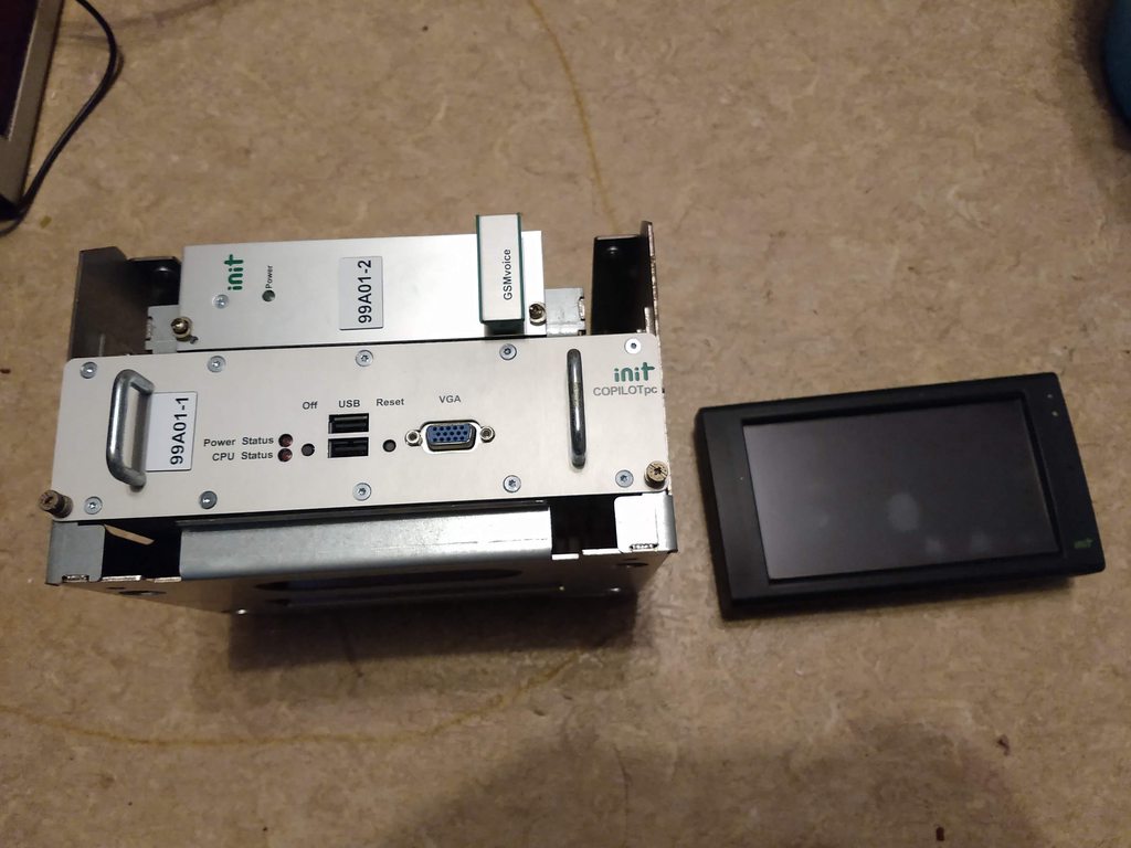
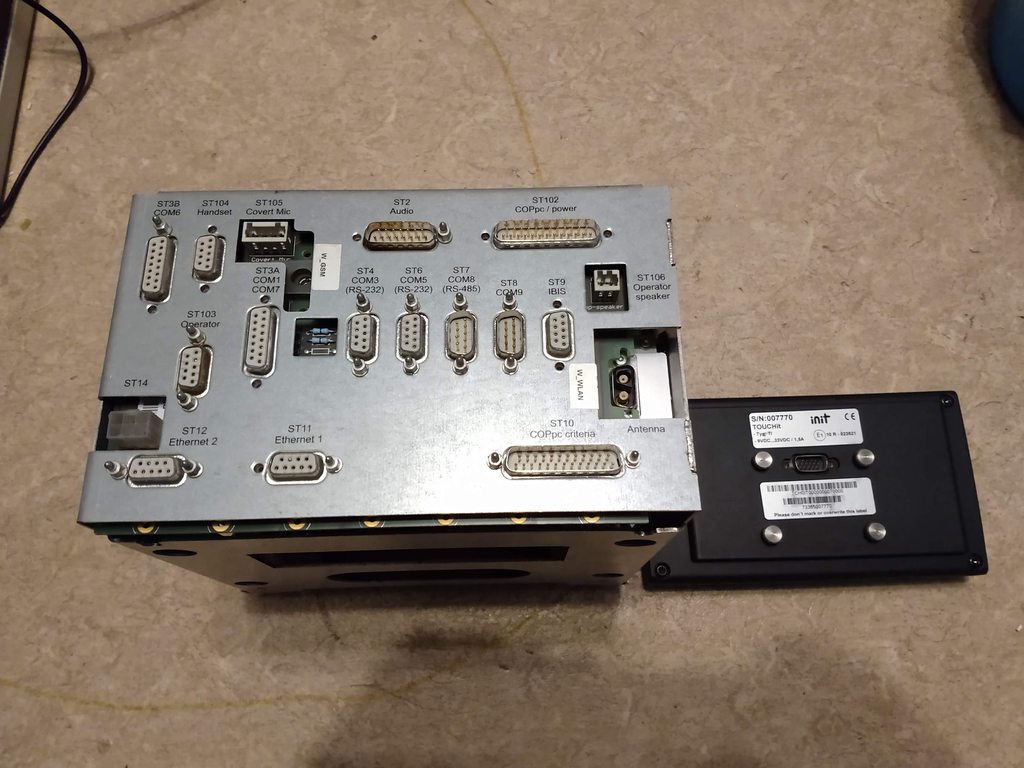
I‘ve one Init COPILOTpc system with a touchpanel (TOUCHit) but without cables. At the back are some desciptions next to the connectors, but no pinout 
Does anyone have pinouts of these connectors so I can make my own cables? Like power, IBIS and where to connect the touchpanel.
|
|
| |
Beitragsbewertung:

|
MagnusMagus

Senator
673 Beiträge
|
RE: Init Copilot PC pinout, 22 Jul. 2020 21:53
|
I think it would be one2one cable for the operator panel.
Operator is ST103.
Power should be easy..just check with the Multimeter for ground or open the cover and find the connectors going to the Fuse.
View my english website about IBIS devices IBIS-INFO.
Geändert von MagnusMagus am 22.Jul.2020 21:55
|
|
| |
Beitragsbewertung:
|
Fien1989
Gelehrter
230 Beiträge
|
RE: Init Copilot PC pinout, 22 Jul. 2020 22:01
|
But the ST103 is DB-9. At the back of the touchpanel is a DB-15 connector. So it can‘t be one-2-one.
Power isn‘t easy like that. I‘ve found the fuse and the ground, but after aplying power to it the power-LED only flash. I suppose there‘s 24vdc needed on a additional pin (switched 24vdc) to let it turn on, like a car radio.
And the ground doesn‘t seem to be connected to the chassis. No single pin it connected to the chassis.
Geändert von Fien1989 am 22.Jul.2020 22:01
|
|
| |
Beitragsbewertung:
|
MagnusMagus
Senator
673 Beiträge
|
RE: Init Copilot PC pinout, 22 Jul. 2020 22:11
|
Oh, sorry... ist not visible on the photo that the panel has a third row :(
Power probably needs a TON signal somewhere on the criteria socket. One way to find it is looking for contacts that have no signal to ground and then bridging those as TON is unusually on while low. But don‘t try it without examining the board. Local criteria ground is unusually bridged across multiple pins.
About the operator panel, I suspect that it has an Ethernet bus connection or a VGA + touch/USB you definitely need a Pinot for that or a lot of free time and an ocziloscope...
|
|
| |
Beitragsbewertung:
|
Fien1989
Gelehrter
230 Beiträge
|
RE: Init Copilot PC pinout, 22 Jul. 2020 23:19
|
Someone told me the touchpanel use RS-485, but I don‘t know if it‘s true.
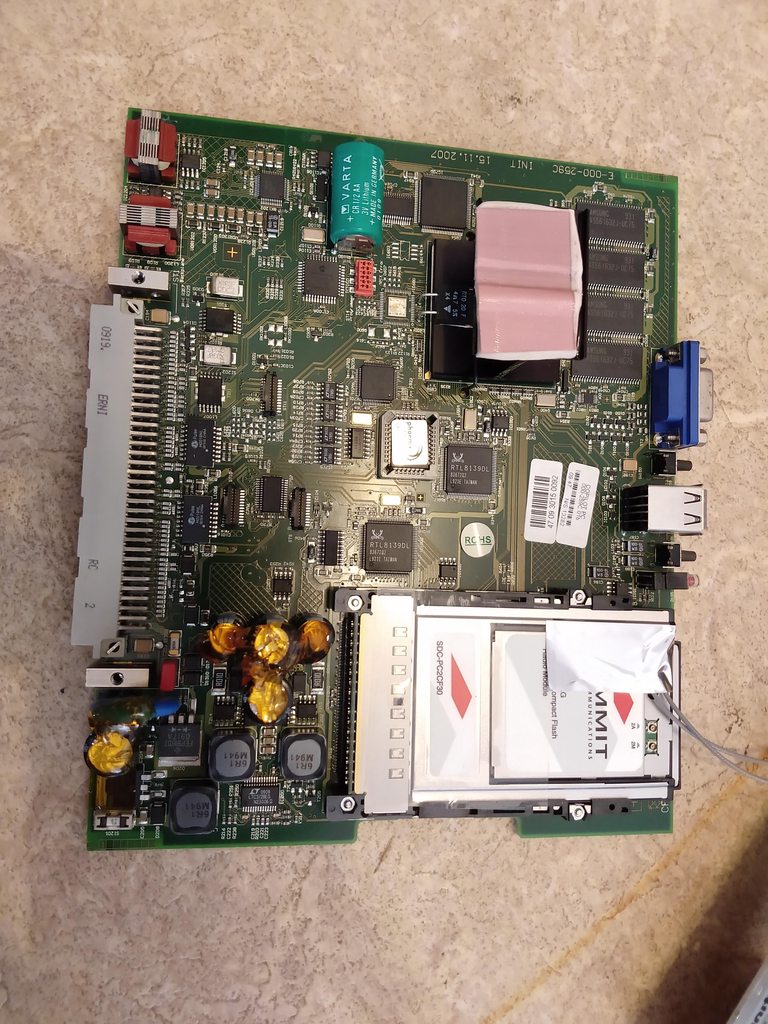
The inside of the COPILOTpc is just a single board, full with small SMD components
|
|
| |
Beitragsbewertung:
|
MagnusMagus
Senator
673 Beiträge
|
RE: Init Copilot PC pinout, 23 Jul. 2020 01:06
|
Looks like an older design, Smith like a pc104 design.
Probably a 486/P1 CPU , maybe VIA Cx or even an AMD 586
|
|
| |
Beitragsbewertung:
|
Fien1989
Gelehrter
230 Beiträge
|
RE: Init Copilot PC pinout, 23 Jul. 2020 01:24
|
But it‘s from 2007 and should have Windows XP Embedded :-o The CF-card is 512MB.
|
|
| |
Beitragsbewertung:
|
MagnusMagus
Senator
673 Beiträge
|
RE: Init Copilot PC pinout, 23 Jul. 2020 01:31
|
The CPU is under the heatsink :)
The realtek 8139 chips are very old I mostly saw those in P1 or P2 Systems. 2006 would probably be some P3 era Celeron with 600-800 MHz tops
Would love to take that device apart ;)
|
|
| |
Beitragsbewertung:
|
Fien1989
Gelehrter
230 Beiträge
|
RE: Init Copilot PC pinout, 23 Jul. 2020 02:14
|
The unit is put back together again :-P
On the heatsink is also a regulator mounted. That one needs to be bend before the heatsink can go of, so I didn‘t touch it.
I‘ve saw Realtek 8139D(L) network chips on P4 era desktop boards as well  The P1 era chips was mostly B/C versions. The P1 era chips was mostly B/C versions.
|
|
| |
Beitragsbewertung:
|
Zugbusmodul

Gelehrter
103 Beiträge
|
RE: Init Copilot PC pinout, 23 Jul. 2020 17:18
|
I have a similar backplane.
"A5-XST102" Kabel "W_PW_CRIT_1"
ST102:
1: +BAT +24V
14: +BAT +24V
13: -BAT 0V
16: -BAT 0V
15: TEIN (Terminal On Signal)
My TOUCHit-Terminal has a D-Sub9 Connector, its connected via Ethernet:
Anschlussbuchse Terminal
1 - weiß-orange
2 - orange
3 - weiß-grün
4 - grün
5 - blau
6 - braun
7 - offen
8 - weiß-blau
9 - weiß-braun
Anschlussstecker Backplane - Ethernet1 "XST11" "W_ETH_PW_1"
Schirm auf Gehäuse
1 - weiß-grün
2 - grün
3 - weiß-orange
4 - orange
5 - blau
6 - braun
7 - offen
8 - weiß-blau
9 - weiß-braun
IBIS-Wagenbus:
W_IBIS_1 Anschlussstecker Sub-D9
2x2x0,5 UNITRONIC LiHCH (TP)
4: gelb
5: grün
6: braun
8: weiß
Schirm an Steckergehäuse
Geändert von Zugbusmodul am 23.Jul.2020 17:19
|
|
| |
Beitragsbewertung:
|
Fien1989
Gelehrter
230 Beiträge
|
RE: Init Copilot PC pinout, 23 Jul. 2020 18:44
|
Is your power connector a DB 26-pin as well?
I connected the -BAT 0V to 13 and 25 because that was the same ground of that from the capacitors. And I didn‘t connected te TEIN, maybe that was why only the power LED flashed?
I‘ll try your pinout when I‘am home
|
|
| |
Beitragsbewertung:
|
Fien1989
Gelehrter
230 Beiträge
|
RE: Init Copilot PC pinout, 24 Jul. 2020 14:08
|
I‘ve left the 0v/ground on 13+25 and didn‘t connect pin 16 because that one isn‘t connected to 13 internally but 25 does.
Then I connected 15 TEIN to 24+ and now the unit starts up
IBIS isn‘t tested yet, I‘ll do it after I have a login code for the system, otherwise the destination can‘t be changed.
And my TOUCHit panel really have 15 PINS, so I still don‘t know how to connect it.


Geändert von Fien1989 am 24.Jul.2020 14:10
|
|
| |
Beitragsbewertung:

|
Zugbusmodul
Gelehrter
103 Beiträge
|
RE: Init Copilot PC pinout, 24 Jul. 2020 17:20
|
My PowerSupply-Connector is a D-Sub 25.
If you read out the CompactFlash-Card with PC you can read the in the "archive"-Folder the DriverCode.dat
|
|
| |
Beitragsbewertung:
|
Fien1989
Gelehrter
230 Beiträge
|
RE: Init Copilot PC pinout, 24 Jul. 2020 21:10
|
Oh, I saw it after I copied the flash card :-P
This is DB-25 too, I was wrong with DB-26 -_-
It seems like the next-stop audio announcement is also build into this CopilotPC... I can see alot of .mp3 files with stops names
Do you know how the audio output pins are? I‘ve tried the "ST106 operator speaker" but that doesn‘t give any sound when switching to a next stop. Maybe it‘s on ST2, but there‘s no pinout of it :(
Also, there should be a door-open connection on one of the connectors? The system now thinks the doors are open and a driver told me the audio announcement won‘t make sound when the door is open. So I need to bridge something to make it think they are closed.
Geändert von Fien1989 am 25.Jul.2020 1:01
|
|
| |
Beitragsbewertung:
|
Zugbusmodul
Gelehrter
103 Beiträge
|
RE: Init Copilot PC pinout, 25 Jul. 2020 19:21
|
Fien1989:
Oh, I saw it after I copied the flash card :-P
This is DB-25 too, I was wrong with DB-26 -_-
It seems like the next-stop audio announcement is also build into this CopilotPC... I can see alot of .mp3 files with stops names
Do you know how the audio output pins are? Ive tried the "ST106 operator speaker" but that doesnt give any sound when switching to a next stop. Maybe its on ST2, but theres no pinout of it :(
Also, there should be a door-open connection on one of the connectors? The system now thinks the doors are open and a driver told me the audio announcement wont make sound when the door is open. So I need to bridge something to make it think they are closed.
I think this could be the pinout of ST2 "Audio", mine has the name "PA Amplifer"
weiß und braun = Lautsprecher Innen ("PA Amplifer 1" -> 4 und 12)
gelb und grün = Schaltkontakt LSP Innen ("PA Amplifer 1" -> 6?? 14, 15 COMMON??)
|
|
| |
Beitragsbewertung:
|
Fien1989
Gelehrter
230 Beiträge
|
RE: Init Copilot PC pinout, 26 Jul. 2020 02:08
|
So you think connecting a loudspeaker between 4 and 12 would be enough?
What does the "schaltkontact" do? Is it only used to switch on a amplifier when sound is played or must I bridge it to enable sound output?
|
|
| |
Beitragsbewertung:
|
Zugbusmodul
Gelehrter
103 Beiträge
|
RE: Init Copilot PC pinout, 26 Jul. 2020 12:19
|
Fien1989:
So you think connecting a loudspeaker between 4 and 12 would be enough?
What does the "schaltkontact" do? Is it only used to switch on a amplifier when sound is played or must I bridge it to enable sound output?
No, you need an amplifer to hear the announcement. I think there are only 775mV output. But it could be enough for a headphone.
"Schaltkontakt" means to enable the amplifer to forward the announcement to the public loudspeakers. Its only an output signal from Copilot to ELA/PA
Geändert von Zugbusmodul am 26.Jul.2020 12:21
|
|
| |
Beitragsbewertung:
|
Fien1989
Gelehrter
230 Beiträge
|
RE: Init Copilot PC pinout, 26 Jul. 2020 23:48
|
Oh, it‘s a line-level signal. Then I‘ll use a amplified speaker instead.
I‘ll try this next week, when my ordered DB-15 connector and socket for audio-connection arrive
|
|
| |
Beitragsbewertung:
|
Fien1989
Gelehrter
230 Beiträge
|
RE: Init Copilot PC pinout, 29 Jul. 2020 23:59
|
Zugbusmodul:
No, you need an amplifer to hear the announcement. I think there are only 775mV output. But it could be enough for a headphone.
"Schaltkontakt" means to enable the amplifer to forward the announcement to the public loudspeakers. Its only an output signal from Copilot to ELA/PA
Thank you very much, this works I‘ve connected these pins to the input of a amplified speaker and the audio announcements works fine now
Geändert von Fien1989 am 30.Jul.2020 0:00
|
|
| |
Beitragsbewertung:
|
|
|